What's in the box?
The following items are shipped with the system:
- (3 feet / 1 meter in length each)
- (3 feet / 1 meter in length)
- (3 feet / 1 meter in length)
- One Ethernet cable
- Power cable
The following table will help you identify the cables included with your Networked VGA Grid purchase. Note these images are for identification purpose only. The cables included with your system may be different with respect length, color, cable casing or shielding.
The cables included with your purchase are not proprietary. If desired, you can use other cables, purchased separately, to capture your sources.
Description of Included Cables (Images are for cable type identification, actual cable appearance may vary.)
| Image | Name | Description |
|---|---|---|
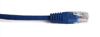 | RJ-45 Ethernet cable | Connects the system to your network. |
Front and back panel view for the VGA Grid
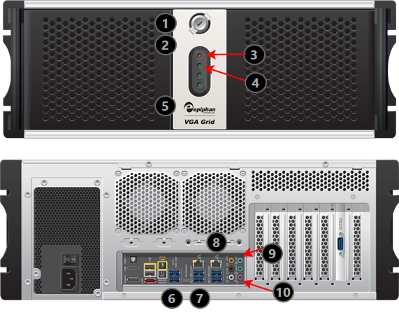
Rackmount Networked VGA Grid Front and Back Panel Descriptions
| Label | Name | Description |
|---|---|---|
| Power Button (behind door) | Unlock the door to reveal the power button. Press to turn on; press and release to turn off the system. Press and hold for 4 seconds for a forced system shutdown. |
 | Reset (behind door) | Unlock the door to reveal the reset button. Cycles the power off then on, like a computer reset button. |
 | Power LED | Indicates the system is powered on. |
 | Hard Drive LED | Blinks when the system is recording or accessing the hard drive. |
 | USB Ports (behind door) | Unlock the door to reveal two USB ports. For connection of external hard drives, flash drives or control interfaces. |
 | USB Ports | For connection of external hard drives, flash drives or control interfaces. |
 | USB Ports | For connection of external hard drives, flash drives or control interfaces. |
 | RJ-45 Ethernet | Auto-sensing gigabit Ethernet 10/100/1000 Base-T network port. |
 | Audio In (blue) | Connect amplified line in audio sources to the system. |
 | Audio In (pink) | Connect unamplified microphone audio sources to the system. |

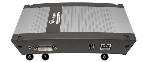
VGA Grid HD Encoder overview
VGA Grid HD Encoders are small portable units with a size of 202 mm × 105 mm × 35 mm (7.95” × 4.13” × 1.38”). Each has one DVI (single link), one S-Video and one audio input.
The following cables come with each VGA Grid HD Encoder you purchase:
- One VGA to DVI-I cable
- One DVI (male) to HDMI (female) adapter
- One DVI-I cable (single link)
- One composite to S-Video cable
- One Ethernet cable
- One Power over Ethernet injector
| Image | Name | Description |
|---|---|---|
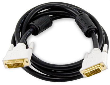
| DVI-I cable (single link) | Connects a DVI source to the encoder’s DVI port(s). |
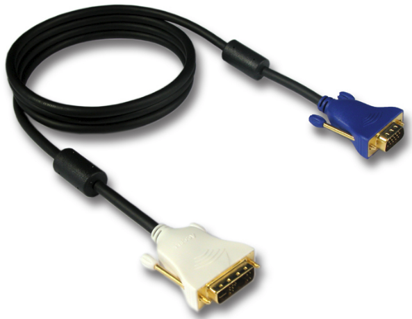
| VGA to DVI cable | Connects a VGA source to the system’s DVI port(s). |
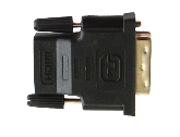 | DVI (male) to HDMI (female) adapter | Connects an HDMI source to the system’s DVI port(s). |
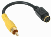 | Composite to S-Video cable | Connects a composite output from an analog sources to the system’s S-Video port(s). |
 | RJ-45 Ethernet cable | Connects the system to your network. |
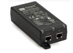
| Power over Ethernet Injector | Injects power over an ethernet cable. Used to power the VGA Grid HD Encoders when the network connection is not powered. |
Front Panel
This section describes the front panel connectors and indicators.
Note, not all connections are used.
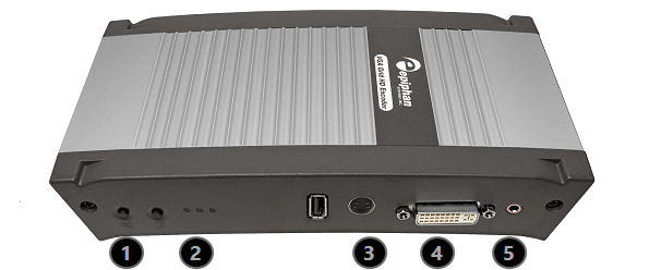
VGA Grid HD Encoder Front Panel Descriptions
| Label | Name | Description |
|---|---|---|
| Reset button | Resets the Networked VGA Grid back to its factory configuration defaults. To ensure the device is not accidentally reset, a special sequence is required. See Perform factory reset. |
| Status LEDs | Three LEDs on the front panel indicate the following Networked VGA Grid status: Solid blue LED indicates device is starting up. Solid green LED indicates the device is ready to capture images. Flashing blue LED indicates:
If the periodic disk check function occurs during start up, it may take up to 20 minutes to power up the device. During this time the blue LED is solid and the green LED flashes. See Storage disk maintenance for more information. |
| S-video input | Connect to an S-video source or a composite video source using the adapter (included). |
| DVI In | Connect to one of the following sources:
|
| Audio In | Connect to an audio input source. |
Back panel
This section describes the back panel connectors and indicators.
VGA Grid HD Encoder Back Panel Descriptions
| Label | Name | Description |
|---|---|---|
| Audio Out | Connect to audio equipment, such as headphones or speakers, to confirm the audio stream is captured. |
| DVI Out | Connect to video equipment, such as a monitor or projector to confirm the video stream is captured. Connect one of the following sources:
This connection can convert a VGA input signal to DVI output signal. |
| RJ-45 | Attach the provided RJ-45 cable and connect to a powered Ethernet port. The port is auto-sensing and supports negotiations at 10/100 speeds. Power over Ethernet is used to power the VGA Grid HD Encoder. If the network connection does not provide power, use the provided power over Ethernet injector to power the device. |
