Control with RS-232 / serial port
Networked VGA Grid presents an RS-232 / serial port control interface
- Connect and configure the RS-232 cable
- Control the Networked VGA Grid with RS-232
- RS-232 / Serial port command examples
Connect and configure the RS-232 cable
To connect your control equipment to
To connect the serial port cable:
- Attach the null modem cable to the control interface.
- Connect the USB to RS-232 serial adapter to the null-modem cable.
- Connect the USB to RS-232 serial adapter to one of the
The only configuration available for the serial port is flow control. Flow control changes the rate of data transfer over the cable. Some communication settings are static and cannot be changed. The static settings are:
- Baud rate set at 19200
- Parity set to none
- Stop bits set to one
To configure serial port flow control:
- Login to the Admin panel as admin. See Connect to the Admin panel.
- Select the Serial Port link in the Configuration menu; the serial port configuration page opens.
- Select Hardware, Software, or None from the drop-down menu. Refer to the table below for a description of the options.
Serial Port Flow Control Options
| Label | Description / Options |
|---|---|
| Hardware | A hardware handshake mechanism is used for flow control. This is also called RTS / CTS flow control. Select this when your control terminal requires it (see control terminal manual). |
| Software | A software handshake that uses XON/XOFF characters to control the flow of data. Select this when your control terminal requires it (see control terminal manual). |
| None | No flow control is used. Only select this if your control terminal requires it (see control terminal manual). |
- Click Apply.
Control the Networked VGA Grid with RS-232
You can use the null-modem cable and your control terminal software to issue commands to
Each command sent to
Some commands require a channel or recorder name as an argument. In those commands, the channel or recorder name is separated from the command name by a period, as shown in the table. The channel name value can be either the name or the index of the recorder or channel. Use of the index is recommended.
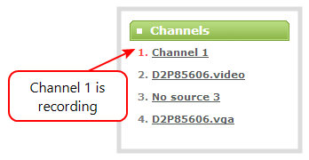
A channel's index is found by looking at the Channels list in the Admin panel. In the screen capture below, the channel with index 1 is currently recording (it's index number is red). To address this channel via RS-232 commands, use the index 1.
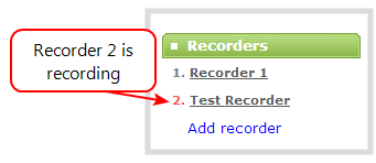
For commands requiring a recorder index, determine your recorder's index by combining the recorder's number with the prefix m. In the example below, the second recorder's index is 2. To access this recorder via RS-232 commands, use the index m2.
The table describes the RS-232 commands supported by
Supported RS-232 Commands
| Command Name | Description |
|---|---|
| Recording Commands | |
START.<channel> START.<recorder> | Starts recording for the provided channel or recorder. This can alternatively be accomplished with the following set commands: SET.<channel>.rec_enabled=on
If the channel is already recording, the current recording is continued. |
| START | Starts recording There is no RS-232 command to restart recording. If recording is already active when the start command is issued, the recording continues. |
STOP.<channel> START.<recorder> | Stops recording for the provided channel or recorder. This can alternatively be accomplished with the following set commands: SET.<channel>.rec_enabled=""
|
| STOP | Stops recording |
| SNAPSHOT.<channel> | Takes a snapshot image of the current channel (supported only if the channel is configured to use the Motion JPEG codec). Snapshots are saved with recording files on the |
| SNAPSHOT | Takes a snapshot image |
| Configuration Commands (see Configuration keys for third party APIs for available keys) | |
GET.<channel>.<key> GET.<recorder>.<key> | Gets the saved value of a given parameter for the specified channel or recorder. |
SET.<channel>.<key> SET.<recorder>.<key> | Sets the value of a given parameter for the specified channel or recorder. The value is not saved until the SAVECFG command is sent. |
| SAVECFG | Saves the parameters modified by the SET command. |
| Status Commands | |
STATUS.<channel> STATUS.<recorder> | Reports the recording status of the specified channel or recorder. Status is one of:
|
| STATUS | Reports the recording status of each channel Status is one of:
|
| FREESPACE | Reports the free storage space, in bytes. |
RECTIME.<channel> RECTIME.<recorder> | Reports the elapsed recording time for the current file on the specified channel or recorder. |
| RECTIME | Reports the elapsed recording time for the current file on each channel. |
Additionally, the
RS-232 Status Changed Messages
| Command Name | Description |
|---|---|
| STATUS. | Provides the status of the recording service
The Uninitialized status is sent when there is an internal error. Check the |
RS-232 / Serial port command examples
The following examples demonstrate how to use some of the RS-232 commands supported by the
Each command sent to
For values with spaces, enclose the value in quotation marks. For empty values, use empty quotation marks with nothing between.
You must always follow a "SET" command in RS-232 with the "SAVECFG" command. Otherwise the new configuration setting(s) will not take effect. See "SET" examples below.
1. To start recording
START
2. To stop recording
STOP
3. To start recording on all channels and recorders:
START
GET.
SET
SAVECFG
SET
SAVECFG
SET
SAVECFG
