Quick Start
This section helps you get up and running quickly with your Networked VGA Grid.
- Step 1: Physical set-up and power-on
- Step 2: Admin discovery and login
- Step 3: Set a static IP address for the encoder
- Step 4: Add the encoder as a channel
- Step 5: Configure the channel
- Step 6: Testing the stream
- Step 7: Recording the stream
Before you get started, make sure you have:
- an HD source (i.e. a computer, a tablet, or a phone)
- the appropriate cables or adapters to convert the output to DVI (if needed)
- a VGA Grid HD Encoder and associated cables
- ideally, a network with Dynamic Host Configuration Protocol (DHCP)
- a computer with a web browser connected to the same network (this is referred to as the “admin” computer in the steps below)
- optionally, an audio source such as a microphone or the headphone jack from a laptop
These instructions include steps for setting up and configuring audio. Skip these optional steps if you do not want to configure an audio source at this time.
Step 1: Physical set-up and power-on
Complete the following steps to prepare and power on the system. Refer to the Front and Back Panel View section for your system to locate the appropriate input ports.
- Turn on your HD source and connect the output cable to
- (optional) Attach a 3.5 mm audio cable from your audio source to the
- If your network connection provides power over Ethernet:
- Connect an Ethernet cable to the VGA Grid HD Encoder. Connect the Ethernet cable to your network.
If your network connection does not provide power over Ethernet:
- Connect one end of the power cord into the PoE injector and the other end into a grounded AC power source.
- Connect an Ethernet cable from the Ethernet switch port to the RJ-45 connector (labeled In) on the PoE injector.
- Connect an Ethernet cable from the the RJ-45 connector (labeled Out) from the PoE Injector to the RJ-45 Ethernet port on the back panel of the VGA Grid HD Encoder.
- Wait for the VGA Grid HD Encoder to complete the power up sequence. The green power LED is illuminated when boot up is complete.
- Connect the Ethernet cable to the Networked VGA Grid.
- Connect the Ethernet cable to your network.
- Attach the power cable to the system and plug it into a power source.
- Unlock the front panel and press the power button to turn on the system.
- Wait for the Networked VGA Grid to complete the power up sequence. The power LED illuminates and the hard drive LED flashes during start up.
Step 2: Admin discovery and login
The Networked VGA Grid is managed from an Admin panel. This interface acts as a configuration utility and system monitor. The first time you access the Admin panel you will not know the IP address of the system.
The steps below use DNS-based service discovery (a type of zero-configuration networking) to access the system. Depending on the operating system on your admin computer you may need to install some software before you can used DNS-based discovery.
This quick start is meant for systems that support DHCP and DNS, however if your system does not support these mechanisms, refer to Connect to the Admin panel and Connect to the Admin panel for alternative discovery mechanisms. Return to step 3 below when you have completed setting a static IP address for the Networked VGA Grid.
Installing Bonjour Print Services
| System | Action Needed |
|---|---|
| Microsoft Windows | You must install Bonjour Print Services:
|
| Mac OS X | The Bonjour software used for service discovery is built in to the Mac OS. No special actions are needed. |
| Linux | The Avahi implementation used for DNS-based discovery is shipped with most Linux distributions. If necessary, check with your administrator to ensure you have the Avahi package installed. |
You are able to access the system Admin panel on the local network by specifying its serial number in a web browser on your admin computer.
- Find the system’s serial number. It is printed on a sticker on the back of the unit.
- Type the following string into the address bar of your web browser on your admin computer (where <serial> is the serial number of your Networked VGA Grid):
http://<serial>.local/admin
For example: http://95dd40d5.local/admin
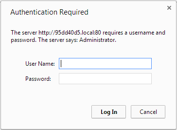
- Enter the user name and password then click OK. The administrative user is ‘admin’. Initially no password is set. To set a password follow the procedure outlined in User administration.
- Optionally, navigate to the Network link under the Configuration heading and note the IP address of the system.
Step 3: Set a static IP address for the encoder
It's recommended that you use static IP addresses for any VGA Grid HD Encoders on your network. Encoders are connected to the VGA Grid by their IP addresses. Using static IP addresses ensures that the encoders can still be located after a system relocation, power failure or other event that may change a dynamically allocated IP address for the encoder.
If you have not already set a static IP address for the VGA Grid HD Encoder:
- Find the VGA Grid HD Encoder's serial number. It is printed on a sticker on the bottom of the unit.
- Type the following string into the address bar of your web browser on your admin computer (where <serial> is the serial number of your encoder):
http://<serial>.local/admin
For example: http://98498.local/admin
- Enter the user name and password then click OK. The administrative user is ‘admin’. Initially no password is set. To set a password, follow the procedure outlined in User administration.
- Navigate to the Network link under the Configuration heading; the network configuration page appears.
- Select the radio button use static address, if not already selected.
- Enter the desired IP Address and Network Mask.
- Enter the Default Gateway address. If you do not have a default gateway for your network, enter the IP address of the Networked VGA Grid that is found on the Network page in its Admin panel.
- Enter the DNS Server address. If you do not have a DNS server, enter the new static IP address of the system.
- Click Apply to save the changes; the changes are saved and a message appears asking you to reboot.
- Select the Maintenance link under the Configuration menu; the maintenance page appears.
- Click the Reboot Now button near the bottom of the page.
Step 4: Add the encoder as a channel
Fresh out of the box, your Networked VGA Grid isn't aware of any VGA Grid HD Encoders on your network. The Admin panel is used to add each encoder as a channel to the VGA Grid.
Whether or not you chose to use a static IP address, the next step is to add the encoder as a channel.
The serial numbers and IP addresses for your system will not be the same as the examples shown below.
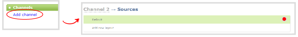
- From the Admin panel, scroll to the Channels section and click Add channel; the add channel configuration page appears.
- From the Admin panel, scroll to the Channels section and click External encoder ; the external encoder selection page appears. Your list should contain just the one VGA Grid HD Encoder set up in Step 1, but if it has several, like the example below, match the serial number with the serial number printed on the bottom of your encoder.
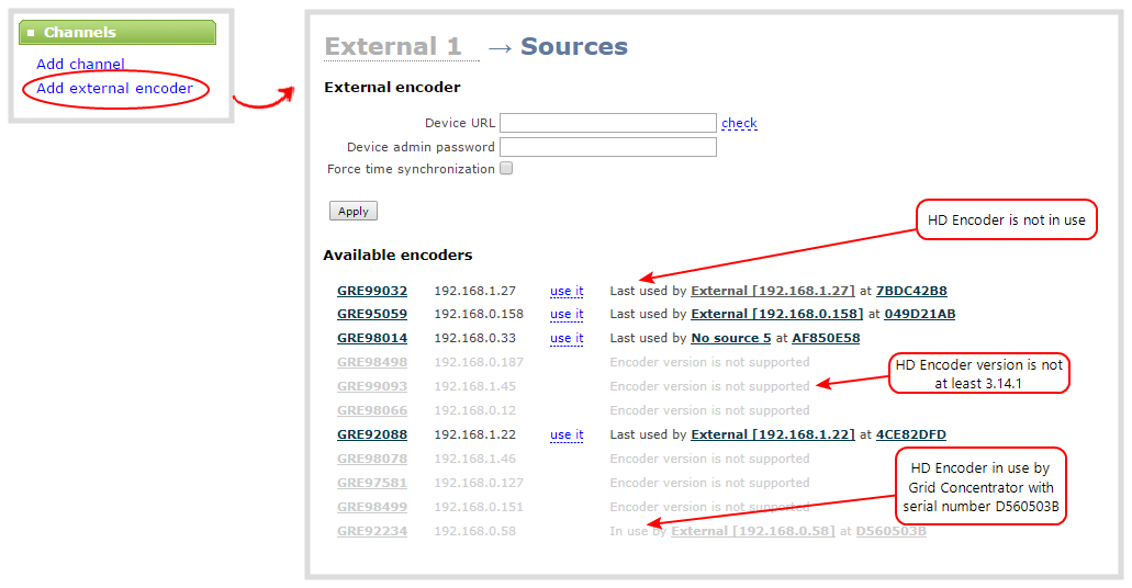
- Copy the IP address for your VGA Grid HD Encoder from the list and paste it in the Device URL field.
- Leave the admin password blank (this is the default) unless you assigned an admin password earlier.
- Click Apply; your channel is added as a new channel named External [<ip address>].
- Click Status to confirm the new name.
- Rename the channel:
- Click on the channel name at the top of the channel configuration window. The name text becomes red.
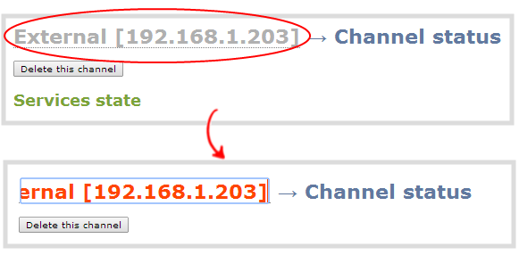
- Edit the name to reflect the VGA Grid HD Encoder serial number, or the data it is capturing. The following characters are supported: a-z; A-Z; 0-9; + (plus); - (hyphen); _ (underscore); , (comma), . (period); ~ (tilde); # (hash); [ ]; ( ). Although spaces are also supported, it is suggested you use underscores to separate words.
- Press Enter on the keyboard. The name is updated at the top of the screen and in the list of channels at the left side.
Step 5: Configure the channel
Now that you have confirmed the system sees your source it is time to
To review and configure the channel:
- From the Admin panel, scroll to the Channels section.
- Click the link for your channel; the channel expands.
- Click Encoding for your channel.
- No need to change anything right now. Review some of the default settings. The four most useful settings to know about are codec, frame size, frame rate and bitrate.
- The codec is set to H.264 by default.
- The frame size should reflect the resolution provided by your source. You can set it to something different by typing in the fields or selecting an option from the different sizes shown. Scaling the image (making it larger, smaller, or different aspect ratio) takes some processing power, so it’s always best to leave this at the value detected by the system unless you know it is wrong or know you need to scale the size.
- The frame rate limit is set to
- The bitrate is set to automatic, and the system will determine the best value.
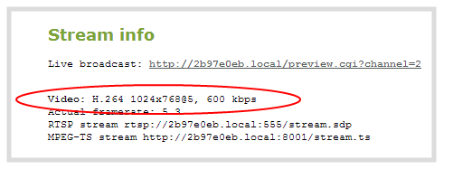
- Click Status for your channel.
- Notice the Stream Info section has an item named Video that reflects the four settings reviewed in prior steps (the frame rate is specified as <resolution size>
You may now optionally add audio to your channel:
- Click Encoding for your channel; the Encoding page is displayed.
- Scroll to the bottom of the Encoding and click the Enable audio checkbox.
- Leave the default AAC format and audio bitrate.
- Click Apply.
Step 6: Testing the stream
The Status page contains a link to the live broadcast stream for your channel.
To preview the channel in a browser:
- From the Admin panel, scroll to the Channels section.
- Click the link for your channel.
- Click the Status link for your channel.
- Right-click on the Live broadcast link for your channel and select Open in a new tab or Open in a new window.
- The new tab or window opens with the stream displayed.
- If the signal is not detected, reset the DVI cable connections and try again.
Your stream setup is complete. Since most of the steps are pre-configured; you are up and running with a stream very quickly. You can share the live broadcast link with your users.
Step 7: Recording the stream
To record the stream:
- From the Admin panel, scroll to the Channels section.
- Click Recording for your channel; the Recording page is displayed.
- Click the red Start button; the text at the top of the screen changes to indicate the recording is starting, then indicates the length of time since the recording started.
- Click the black Stop button; the recorder stops.
- Refresh the page by clicking Recording again; the page reloads and a file list appears that shows your newly recorded stream snippet.
- Click the file name to download and view your recording.
What’s Next?
Now that you have a source set up and ready to stream, you can fine-tune the system to your exact requirements. You can look at topics such as:
- Create an HD Encoder channel
- Add an HD Encoder as a source (custom channel)
- Add a video source (custom channel)
- Create a custom channel
- What is streaming?
- File and recording transfer
- User administration
When you have completed system tuning, make sure to back up the system configuration using the procedure described in:
Refer to the table of contents for a complete list of the topics covered.
