
Audio matters
Compelling video is essential to hold the attention of viewers but without an audio recording (or audio track), your video will feel a little empty. The audio for your video could be many things – the speech of actors in the video, live music, voice over narration or mix of any of these things and more.
No matter what the audio content, poorly captured and recorded audio distracts the viewer just as much as poor video quality and either may cause them to stop viewing.
Learning through an example
The information contained in this paper, while applicable to many audio situations, is specific to encoding/recording of analog audio into a digital format.
For example, let’s assume you have been hired to record and stream a live event that features a folk singer playing an acoustic guitar. The performer has an analog mixer from which you will receive your audio feed.
The specifications on the analog mixer are:
- 0 VU = +4 dBu
- Maximum output = 21 dBu
The analog audio input specifications on the digital recorder you are using is:
- Maximum input level = 0.707 V RMS
- Input gain adjustment = 0 to 30 dB
What do those values mean and how will you make sure the audio performance is properly encoded and recorded? To communicate effectively with the sound technician in this example or any other live streaming and recording event, you need to have a good understanding of the terms, language and measurement units used to represent audio levels in their world.
This paper provides you with the terminology and knowledge needed to ensure your recording and live stream contain the best possible audio quality.
What is “audio quality”?
Audio quality is subjective, but most people can agree that good audio quality is clean, distortion free and played at a comfortable volume.
Clean audio is typically defined as being free of any audible noise, hiss/buzz or interference like background sounds. The equipment and techniques used to capture clean audio are beyond the scope of this paper – your audio engineer will set up the analog audio equipment to provide relatively clean audio for you to digitize and record. This discussion focuses on encoding and delivering this high quality to the listener.
Distortion is often introduced into audio through clipping, which is caused by improper signal levels. While distortion is often used to great creative effect (e.g. overdrive of guitar amplifiers), it is definitely to be avoided in the audio encoding process.
A comfortable listening level means that a single playback volume level enables the listener to clearly hear the quieter parts while ensuring the louder parts don’t sound uncomfortably loud. Playback volume level should require minimal amplification to avoid introducing noise in the reproduction.
Poor audio quality draws attention to itself while good audio quality typically goes unnoticed, enabling the listener to focus on the message contained within the audio.
Audio signals
Everyone knows what audio signals sound like, but to understand how they behave it is useful to also know what they look like. While there is no real substitute for actually listening to the audio, visual representations can provide quick insight to the structure of an audio signal. Visuals can confirm what you are hearing and can allow you to detect issues in environments where listening is difficult.
Viewing Audio Signals
The following audio sample is the voiceover track from an Epiphan-produced video which promotes our all-in-one live production mixer product, Pearl.
In this visual representation of the signal, you can clearly identify the speech from the pauses and the peaks in amplitude (level). Listen to the sample below and notice that the audio has the three qualities we identified earlier:
- clear,
- distortion free, and
- neither too loud nor too quiet.

Audio sample – clean audio
When we zoom in on a smaller section of this audio sample you can see that the signal is continuously varying and that individual changes are not very abrupt, but rather rounded in shape. Presence of very straight transitions (either vertical or flat/horizontal) are indications of distortions of the original signal.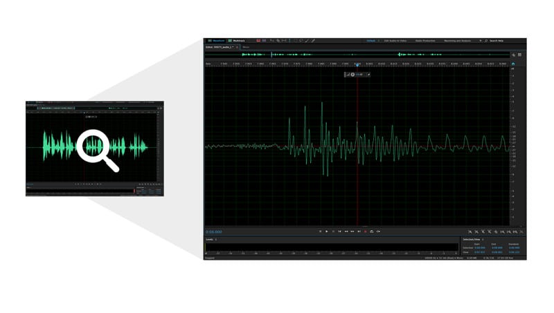 We used Adobe Audition to present these visual representations of our audio signal, but almost any audio editing software works. If looking for a low-cost audio software, Audacity is a free program you use to view and analyze your recorded audio signals.
Audio measurement units
Audio signals have a variety of measurement units. For example, a microphone that detects sound waves and converts them to electrical signals specifies its input in terms of sound pressure level and its output in terms of voltage. For the purposes of this discussion we are concerned with specifying and measuring audio signals in the electrical domain, using units of either Volts or decibels.
Introducing decibels
While circuit designers are accustomed to working with the voltage levels of audio signals (expressed as Volts (V) or millivolts (mV)), these units are inconvenient to audio engineers for a couple of reasons.
The first reason is that the audible range of an audio signal is quite large. Measurement using a linear scale (on which Volts are based) necessitates the use of very broad ranges of values to represent the audio signal levels of interest. For example, 0.7 mV to 25000 mV represents the range of signals typically found in an audio recording. A more convenient scale of measurement would describe this signal range with a narrower scope.
The second reason voltage levels are inconvenient for audio engineers is that for humans, perception of audio signal levels is not linear. A 1 Volt signal increase is dramatic for quiet signals and undetectable for loud signals. A more convenient scale of audio signal measurement is needed to better align the audio signal strength with the perception of the human listeners.
The unit of decibels addresses both of these issues. Decibels use a logarithmic scale that more conveniently represents the wide range of input signals encountered.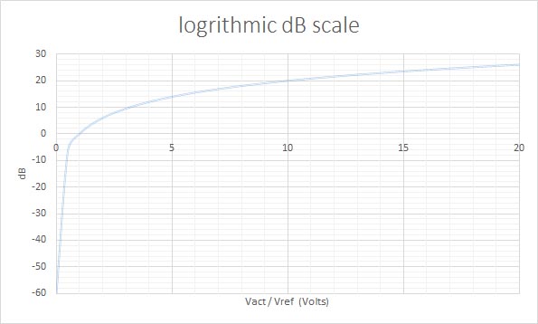
Details of decibels
The decibel is defined as:
dB = 20 * log10 (Vact/Vref) where Vact is the actual voltage and Vref is a known reference voltage
db = 10 * log10 (Pact/Pref) where Pact is the actual power and Pref is a known reference power
It is not necessary to convert between units of volts (or watts in the case of power) and decibels very often, however there are plenty of easily searchable web tools to perform these calculations for you, if required.
Absolute vs. Relative measures
By definition, the decibel (dB) is a measure of the difference between two signals: actual and reference.
The reference value is often implied or unspecified. For example, “We have 18 dB of headroom” implies a specific reference value, which is the clipping point (the point at which the audio will become distorted) and that the actual value (sound level) is 18 decibels below this clipping point.
By contrast, “The signal is 20 dB too low” implies a reference signal which is desired, but unspecified. The actual level in this case is 20 dB below that unspecified, desired level. Saying “I need 10 dB of attenuation” again implies an unspecified desired reference value which is 10 dB lower than the current actual level (attenuation lowers the audio level).
For specification of absolute values, derivative units are defined which refer to a specific, absolute reference level. There are two very common reference voltages for audio signals:
- The first reference value is 1 Volt. When this is used as the Vref variable in the formula above, the resulting unit is dBV (dB referenced to 1 Volt).
- The second common reference value is 0.775 Volts, which results in the unit dBu when used as the Vref variable in the formula above.
These units of measurement (dBV and dBu) are used to specify absolute values (e.g. +4 dBu), as opposed to relative values (e.g. 10 dB of attenuation).
Since both dBV and dBu are often used to specify audio signal levels, it is sometimes necessary to take care when distinguishing one from the other. Due to the logarithmic nature of the decibel, the resulting difference between a signal measured in dBu and dBV is always 2.2 dB (0 dbV = 2.2 dBu). Fortunately, this small difference can be ignored in many situations as it should be built into the margin you leave for error/chance.
Nominal and common absolute values
Audio signals span a wide range of levels, from roughly -60 to +30 dBu. It isn’t practical to design a single circuit to properly accommodate such a broad range, therefore each piece of audio gear is designed to operate optimally on signals which fall into a more narrow range of values. The ideal (average) value of this narrow signal range is referred to as the nominal value.
Audio processing systems (e.g. pre-amps, mixers and other so-called line-out devices) typically output audio signals at relatively high levels (approximately -15 dBu to +5 dBu). By contrast, microphones output much lower signal levels (approximately -60 dBu to -40 dBu). This difference in output gives rise to the common terms “line level” and “mic level”.
While there is no single absolute level for “line level” signals, there are some common options. Professional audio gear typically outputs at either +4 dBu or 0 dBu while some more consumer-oriented gear outputs at -10 dBV (-7.8 dBu). Therefore, “line level” signals may differ by as much as 12 dB depending on the gear being used.
Microphone levels vary significantly also, but are generally not below -60 dBu and not more than about -20 dBu. A microphone pre-amp accepts mic level signals and amplifies these signals to output at line level.
Most professional audio gear specifies input and output levels using dBu or dBV units. However, there is some gear that specifies signal levels in terms of voltage. This may be average root mean squared (RMS) voltage, peak voltage or peak-to-peak voltage. In any case, it is easy to convert these levels to dBu using the formulas above or the many websites and apps available online.
Audio engineers are typically concerned with signal levels measured from -60 dBu to +30 dBu, relative to a reference level of unity (0 dB) that is established by convention and chosen by the equipment vendor.
Dynamic Range
We often speak of audio signal levels as though they are constant. However, we can see from the visualization of our sample audio clip that this is not the case. How can we assign a singular value to a signal which varies so greatly, so quickly and so unpredictably?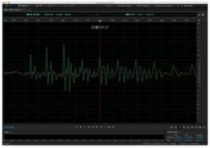
Instead of describing the signal with a singular value representing “the signal level” (which obviously changes greatly over time), we use two values.
- The first is an average (RMS) value of the level and is expressed in absolute values (e.g. +4 dBu).
- The second value is called dynamic range and represents how much the signal varies from that average value, expressed in dB (the implied reference value is the RMS value).
For example, if I have a signal which has an average (RMS) value of -20 dBu but has peaks at -7 dBu, its dynamic range would be 13 dB (-7 dBu minus -20 dBu).
While RMS value and dynamic range certainly don’t capture all properties of the audio signal (e.g. frequency content), they describe it well enough for many audio processing functions such as mixing, amplification and recording.
Clipping
Why is it important to describe the signal with both the RMS value and the dynamic range? Why isn’t the average (RMS) value sufficient to describe the signal? The answer is clipping.
What is clipping?
Every piece of electronic audio equipment has an absolute upper limit to the level of signal it can accept, process through its circuits and produce as its output. If the signal exceeds any of these limits it will be “clipped”. This upper limit is often called the clipping point.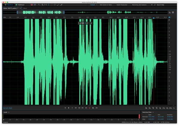 It may seem from the diagram above that clipping a signal merely prevents the signal from reaching its maximum amplitude and therefore simply results in slightly quieter audio. This is not the case. Clipping the signal does not just change its amplitude, it distorts the signal (adding harmonics which are not present in the original signal). Once a signal is clipped it is changed forever – there is no way to recover the original signal.
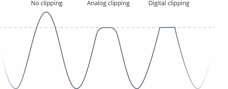
As the signal approaches the clipping point, analog systems begin to round off the signal more gradually toward the clipping point. Digital systems, by contrast, generally clip the signal much more abruptly, allowing the signal to increase at its natural rate until it hits the clipping point. For this reason, analog clipping is said to be more forgiving or “less harsh” than digital clipping. This assessment is somewhat true, but in the process of mixing and recording audio, clipping (both analog and digital) is best avoided altogether when possible.
Below is the same clip of audio, but amplified to the point where the peaks of the signal are exceeding the clipping point. Listen to the recording to hear how clipping the signal introduces very unpleasant audible distortions of the audio.

Audio sample – what does clipping sound like?
How to avoid clipping
Avoiding clipping is usually a matter of ensuring proper setup of all of the equipment along the audio signal chain. This includes everything from the microphone (or other sound source) to the recording medium and/or loudspeakers.
To avoid clipping it is essential to:
- Know the RMS level and dynamic range of the signals you are dealing with, and
- select and setup equipment to provide for sufficient headroom for those signals.
In short, if the levels are exceeding the clipping point in any one piece of equipment, turn the signals down until the peaks are always below the clipping point.
This sounds simple enough, but there are some other issues to consider.
- “When I turn down the levels to avoid clipping, parts of the audio are now too quiet to be heard.”
- “The first speaker at the podium was fine, but the next one was much louder which caused clipping.”
- “During the sound check the levels were great, but during the performance everything was somehow louder which caused clipping.”
In the first case, turning down levels to avoid clipping not only affects the peaks (loud portions) of the signal, but also reduces the level of the quieter portions of the signal. This could mean that certain quieter parts of speech become inaudible or that certain instruments which are mixed in at low levels are no longer heard. There is a limit to how far you can reduce the levels and still have all portions of your audio remain clearly audible.
The second case illustrates that the signal may not be constant over time – especially when changing speakers at a podium or bands on a stage. The quick fix to prevent clipping in these situations is to adjust levels during the performance to adapt to the new speaker at the podium, but this is a reactive and unrealistic solution which requires you have already recorded the audio before making such an adjustment to the signal.
The third case is similar to the second case, with one major difference: there is only one band or speaker at the podium. However, even if there is only a single individual or group at the podium, their sound levels may change throughout the event. It is common for speakers (or bands) to begin calmly and become more animated in their speech/playing as the event progresses, causing both the RMS and peak levels to increase substantially. Once again, adjusting for this scenario in the moment is not a great solution. By the time you realize the signal needs to be turned down, clipping has already occurred.
Fortunately, there are some signal processing techniques that can help with these situations.
Signal Processing
Hardware and software effects can be deployed to shape the audio signal to provide cleaner, more pleasing sound for your audience and ensure protection of your equipment against damaging signal levels.
The three most common signal processing effects are:
- equalization,
- compressors, and
- limiters.
Equalization
So far in this paper we have only been concerned with adjusting levels of the entire audio signal equally. Equalizers are devices (hardware or software) which deliberately adjust different frequencies of the audio signal by different amounts.
Equalizers (or EQ as they are often called) are used to enhance signal quality and address particular issues such as feedback.
The purpose of EQ is to “shape” the sound of the signal, which involves adjusting levels in various frequency ranges, not to adjust the overall (RMS) level of the signal, nor to significantly affect its dynamic range.
It is very common for an audio mixer to have some EQ capabilities. These capabilities may include high pass filtering on inputs and low, mid and high frequency range level adjustments. A dedicated Equalizer typically offers more detailed control, providing many more frequency bands.
Like many topics in this paper, entire books have been written on equalization. EQ is only mentioned in this paper to clearly define it from other signal processing hardware/software, such as compressors and limiters.
Compressors
Compressors are used to reduce the dynamic range of an audio signal. The idea is to reduce the loudest peaks and nudge up the quietest sections to create a signal which does not vary as much. You must apply this effect subtly because the peaks and valleys of the signal level are an important part of the auditory experience. You only want to tame these peaks and valleys to the extent needed to provide a signal which is comfortable to hear and relatively easy to process.
For live streaming or an in-room live experience, compression needs to be applied in real time and is often implemented with dedicated gear. However, if your audience will only hear the recorded copy of the audio then it is often preferable to record without compression (leaving lots of headroom to avoid any clipping) and then apply compression during the post-production phase. The recent shift from 16-bit analog to digital (A/D) conversion to 24-bit A/D conversion means that you can be very conservative with levels (leaving lots of headroom) and still have a very full and dynamic signal for post-production.
Limiters
Many people confuse compressors with limiters, but they are in fact different effects for different purposes. A limiter is meant to limit the peak levels of the audio signal. Unlike compression, it is not intended to reduce dynamic range so much as to prevent the occasional large peak from making it through the system to your amplifier and/or speakers. In most audio setups, limiters are placed immediately after compressors in the signal chain.
You can think of the limiter as a “controlled clipping” function. Its job is to identify signals which are sure to be clipped (for example further down the line when amplified) and to trim them as gracefully as possible. Ideally there wouldn’t be any large signal peaks at this point in the signal chain, but in practice it is extremely difficult to fully prevent such peaks from occurring on occasion – a limiter is used in anticipation of these peaks.
The limiter is used primarily to protect the downstream equipment (amplifier and speakers) from damaging signal levels. It is not used to enhance the signal (unlike compression and EQ), but rather to degrade it in a controlled manner when absolutely necessary.
Amplifiers
The audio amplifier is used to increase the audio signal from the “signal processing” levels mentioned earlier (e.g. +4 dBu) to much higher levels before the signal is applied to loud speakers. The goal of the audio amplifier is to produce an output signal which matches the input signal in all areas except in amplitude. All deliberate modification of the audio signal shape or content is performed upstream in the mixing, EQ, compression and limiting stages of the signal chain.
Input/Output Specifications
Every piece of signal processing gear (e.g. mixers, encoders, recorders, amplifiers) specifies a range of acceptable signal levels for its audio input/output ports. These level specifications enable users to determine how easily these pieces of signal processing gear can be connected together to create a high quality signal processing chain.
Ideally, the output specifications on one piece of equipment would align perfectly with the input specifications of the next downstream gear, but in practice this is not always the case. Users therefore need to understand these specifications and determine any specification mismatches and how best to remedy them.
Although not explicitly stated, input and output specifications are typically valid for a 1 KHz sine wave test signal (an artificially-created sound used to test audio signals).
Input Specifications
Input specifications are often in the form of a maximum signal limit, and they specify what may be connected to the input ports. These specifications may also include the amount of input attenuation or gain available to adjust incoming signals to ideal/nominal levels.
The maximum signal limit indicates the point at which distortion (clipping) of the incoming signal will occur. This limit may be specified in terms of voltage (RMS, peak, peak-to-peak) or dBu.
Output Specifications
Output specifications are often in the form of two values: nominal output and maximum output. The nominal output is the RMS (average) value for a signal when the meter is reading 0 VU. The maximum output indicates the highest value a signal can reach before it begins to distort (clip).
Metering
Analog Meters
Analog meters are usually referred to as “VU Meters”, and provide a general sense of signal loudness by displaying the RMS value of the signal. These meters are designed to have slow attack and gain, therefore they don’t respond to short term peaks, but rather represent longer term average values.
The ideal value is located centrally in the scale (the 0 VU point) with all other points on the meter indicated in dB from this reference point. It is good practice to operate your equipment so the input and output signals are adjusted to be very near the 0 VU point. Your equipment will function at its best around this level.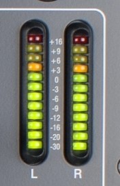 Colored lights are used to provide an easy visual reading of the meter. Green indicates levels at or below the 0 VU point, yellow indicates levels significantly above the 0 VU point, and red indicates levels which are very close to clipping. With ideal equipment operation, the green light holds steady and the first yellow light or two occasionally lights up.
Digital Meters
Digital meters are also sometimes referred to as VU meters, but they are organized differently than their analog counterparts.
The scale of a digital meter places 0 at the very top and this represents the clipping point. Unlike analog VU meters where 0 is the signal level target, with a digital meter you will want to keep your levels well away from 0.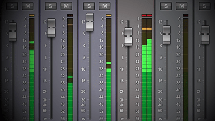 The units used on a digital meter are dBFS (dB relative to full scale). All other points on the meter indicate the number of dB below the full scale (clipping point). Similar to the analog meters, green, yellow and red lights are used to provide easy reading of the current signal level.
- Green is typically reserved for signals which are -18 dBFS or less,
- yellow is for signals between -9 dbFS and -18 dBFS, and
- red represents signals above -9 dBFS.
Digital meter response can vary widely. As with analog VU meters, digital meters provide a slow response to reflect average values. There are also peak meters, which show current peak values, and quasi-peak meters, which provide a balance between peak values and longer term averages. It should be noted that very few meters show absolute or true peak values, therefore caution should be exercised to avoid digital clipping.
In some cases, a separate LED is used to indicate that clipping has occurred. Although this cannot reflect how badly the signal is being clipped (duration and amount), it is nonetheless a very handy indicator.
Analog/Digital Meter Alignment
When using analog equipment (e.g. a mixer) to feed digital equipment (e.g. an encoder/recorder) you want to align the output of the analog meter (ideally at 0 VU) to approximately -18 dBFS on the digital meter. This is a good starting point for setup, and you can then monitor using your meters to ensure that you have appropriate headroom for your signal(s).
Signals which have already had compression applied (e.g. mastered music) often require significantly less headroom than live music signals. However, with modern digital equipment there is little to gain by trying to limit the headroom to what is strictly required by the signal; it’s better to play it safe and leave more headroom than necessary whenever possible.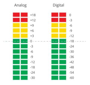
Example Scenario
Let’s get back to the example scenario and some of this information into practice.
Recap: you’ve been hired to record and stream a live event which is a folk singer playing an acoustic guitar. The performer already has an analog mixer from which you will receive your audio feed.
The specifications on the analog mixer are:
- 0 VU = +4 dBu
- Maximum output = 21 dBu
The analog audio input specifications on the digital recorder you are using is:
- Maximum input level = 0.707 V RMS
- Input gain adjustment = 0 to 30 dB
The first thing you’ll need to do is convert the input specification on the digital recorder to be expressed in dBu so you can compare it to the level expected to be received from the analog mixer. This can be done with the formulas provided above or by using any number of online converters.
Maximum input (dBu) = 20 * log (0.707/0.775) = -1 dBu
In comparing the maximum input specification of the digital recoder (-1 dBu) with the expected output level of the analog mixer (+4 dBu) we can see we have a problem. The RMS output of the mixer is expected to be +4 dBu which is higher than the maximum input specification of the recorder. Inputting this signal directly to the recorder will result in clipping because the signal is too high (too hot) for the recorder. To remedy this we’ll need to insert an attenuator (also sometime referred to as a pad or an attenuation pad) between the analog mixer output and the recorder input. This enables us to reduce the level of the signal coming from the mixer to a level which is better suited to the recorder.
The next step is to calculate how much attenuation is required. For this we need to know how much headroom we will need for our signal. With a folk singer and his acoustic guitar I expect that 15 dB of headroom will be plenty. In order to have 15 dB of headroom our analog audio input to the recorder will need to be 15 dB below the maximum input specification of -1 dBu. In other words, the input must be below -16 dBu. Therefore, the attenuator needs to reduce the mixer output signal by about 20 dB. We could select a 20 dB attenuator, but I recommend leaving a little extra margin and choosing a 25 dB attenuator. The 25 dB attenuator will bring the level of the mixer output down to -21 dBu. We then set the input gain adjustment in the recorder to +5 dB to bring the signal level to our desired -16 dBu.
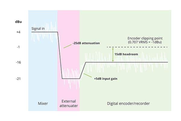
We are now set up to have 15 dB of headroom on our audio signal in the digital recorder. While this level should be plenty, choosing a slightly larger attenuator than we required gives us some extra margin in case we find we need more than 15 dB of headroom (that’s what the sound check is for) or in case the level coming out of the mixer is a little higher than 0VU (+4 dBu). If this is the case we simply re-adjust the input gain on the digital encoder to accommodate.
Summary
Being familiar with the nature of audio signals (RMS + dynamic range) and the various units of measure associated with them you are able to read and interpret audio equipment input/output specifications and determine how set up your digital recorder to ensure the best quality recording possible. You are also able to speak with audio professionals using the proper terms and know which questions to ask to make sure there are no surprises in the audio signal they are providing to you.